

Knowing the heat-affected zone can improve the welding quality, and the welding seam quality standards are explained in detail
- Categories:Industry News
- Author:
- Origin:
- Time of issue:2021-07-29 17:13
- Views:
Knowing the heat-affected zone can improve the welding quality, and the welding seam quality standards are explained in detail
(Summary description)
Welding heat affected zone
The welded joint is a welding consisting of three parts: the weld, the fusion zone and the heat-affected zone.
Welding heat-affected zone: referred to as HAZ (Heat Affect Zone), under the action of welding heat cycle, the area where the solid base metal on both sides of the weld undergoes significant changes in structure and performance is called the welding heat-affected zone.
Microstructure distribution of hardened steel
Features: Martensite is not easy to form under welding air cooling conditions. Such as low carbon steel, 16Mn, 15MnV and 15MnTi, etc.
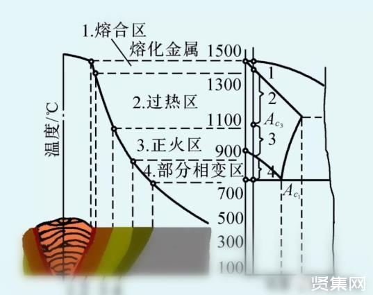
According to heating temperature and organizational characteristics, it can be divided into four areas: overheating zone, normalizing zone, partial normalizing zone and recrystallization zone. as the picture shows.
Overheating zone (coarse crystal zone)
The temperature is between the solidus to 1100°C, and the width is about 1 to 3 mm. During welding, the austenite grains in this area grow up severely. After cooling, a superheated structure with coarse grains is obtained, and the plasticity and toughness are obviously reduced.
Phase change recrystallization zone
Phase change recrystallization area (normalizing area or fine-grained area)
The temperature is between 1100℃~Ac3, and the width is about 1.2~4.0mm. Air cooling after welding makes the metal in this area equivalent to normalizing treatment, so its structure is uniform and fine ferrite and pearlite, and its mechanical properties are better than the base material.
Incomplete recrystallization zone
Incomplete recrystallization zone (also called partial normalizing zone)
The heating temperature is between Ac3 and Ac1. When welding, only part of the structure is transformed into austenite; after cooling, fine ferrite and pearlite are obtained, and the rest is still the original structure, so the grain size is uneven and the mechanical properties are also poor.
Recrystallization zone
If the base material undergoes cold working deformation before welding, the temperature is between Ac1~450℃, and there is a recrystallization zone. The mechanical properties of the metal in this area have not changed much, but the plasticity has increased. If there is no cold plastic deformation before welding, there is no recrystallization zone in the heat-affected zone.
Weld quality standards and the first, second and third level classification of welds
1. Guaranteed items
1. Welding materials should meet the design requirements and relevant standards, and the quality certificate and baking records should be checked.
2. The welder must pass the examination and check the qualification certificate and assessment date of the welder's corresponding welding conditions.
3. Welds of class I and II must be inspected by flaw detection, and should meet the design requirements, construction and acceptance specifications, and check the weld flaw detection report.
4. The surface of the welded seam should not have cracks, weld bead, burn through, arc crater and other defects. Class Ⅱ welds must not have defects such as surface pores, slag inclusions, arc craters, cracks, arc scratches, etc., and class Ⅰ welds must not have defects such as undercuts and insufficient welds.
2. Basic items
1. Appearance of weld seam: uniform weld seam appearance, smooth transition between weld bead and weld bead, weld bead and base metal, and clean welding slag and spatter.
2. Surface pores: Class Ⅰ and Ⅱ welds are not allowed; for class Ⅲ welds, the allowable diameter of each 50mm length of the weld is ≤0.4t; and there are 2 pores ≤3mm; the spacing of pores is ≤6 times the diameter.
3. Undercut: Class I welds are not allowed.
Class Ⅱ weld: depth of undercut ≤0.05t, and ≤0.5mm, continuous length ≤100mm, and total length of undercut on both sides ≤10% of weld length.
Grade III weld: undercut depth ≤0.lt, and ≤lmm.
Note: t is the thinner plate thickness at the joint.
4. The allowable deviation items are shown in Table 5-1.
3. Finished product protection
1. Don't hit the joint after welding, and don't water the steel that has just been welded. Slow cooling measures should be taken at low temperatures.
2. It is not allowed to ignite the arc on the base metal outside the weld at will.
3. Welding can only be performed after the various components are calibrated, and the shim and fixtures should not be moved at will to prevent the size deviation of the components. The welds of concealed parts must go through the concealed acceptance procedures before proceeding to the next concealed process.
4. It is not allowed to clean the slag immediately after low-temperature welding, and it should be done after the welding seam cools down.
Fourth, the quality issues that should be paid attention to
1. The size exceeds the allowable deviation: For the deviation of the weld length, width, thickness, center line offset, bending, etc., the relative position and size of the welding part should be strictly controll
- Categories:Industry News
- Author:
- Origin:
- Time of issue:2021-07-29 17:13
- Views:
Welding heat affected zone
The welded joint is a welding consisting of three parts: the weld, the fusion zone and the heat-affected zone.
Welding heat-affected zone: referred to as HAZ (Heat Affect Zone), under the action of welding heat cycle, the area where the solid base metal on both sides of the weld undergoes significant changes in structure and performance is called the welding heat-affected zone.
Microstructure distribution of hardened steel
Features: Martensite is not easy to form under welding air cooling conditions. Such as low carbon steel, 16Mn, 15MnV and 15MnTi, etc.
According to heating temperature and organizational characteristics, it can be divided into four areas: overheating zone, normalizing zone, partial normalizing zone and recrystallization zone. as the picture shows.
Overheating zone (coarse crystal zone)
The temperature is between the solidus to 1100°C, and the width is about 1 to 3 mm. During welding, the austenite grains in this area grow up severely. After cooling, a superheated structure with coarse grains is obtained, and the plasticity and toughness are obviously reduced.
Phase change recrystallization zone
Phase change recrystallization area (normalizing area or fine-grained area)
The temperature is between 1100℃~Ac3, and the width is about 1.2~4.0mm. Air cooling after welding makes the metal in this area equivalent to normalizing treatment, so its structure is uniform and fine ferrite and pearlite, and its mechanical properties are better than the base material.
Incomplete recrystallization zone
Incomplete recrystallization zone (also called partial normalizing zone)
The heating temperature is between Ac3 and Ac1. When welding, only part of the structure is transformed into austenite; after cooling, fine ferrite and pearlite are obtained, and the rest is still the original structure, so the grain size is uneven and the mechanical properties are also poor.
Recrystallization zone
If the base material undergoes cold working deformation before welding, the temperature is between Ac1~450℃, and there is a recrystallization zone. The mechanical properties of the metal in this area have not changed much, but the plasticity has increased. If there is no cold plastic deformation before welding, there is no recrystallization zone in the heat-affected zone.
Weld quality standards and the first, second and third level classification of welds
1. Guaranteed items
1. Welding materials should meet the design requirements and relevant standards, and the quality certificate and baking records should be checked.
2. The welder must pass the examination and check the qualification certificate and assessment date of the welder's corresponding welding conditions.
3. Welds of class I and II must be inspected by flaw detection, and should meet the design requirements, construction and acceptance specifications, and check the weld flaw detection report.
4. The surface of the welded seam should not have cracks, weld bead, burn through, arc crater and other defects. Class Ⅱ welds must not have defects such as surface pores, slag inclusions, arc craters, cracks, arc scratches, etc., and class Ⅰ welds must not have defects such as undercuts and insufficient welds.
2. Basic items
1. Appearance of weld seam: uniform weld seam appearance, smooth transition between weld bead and weld bead, weld bead and base metal, and clean welding slag and spatter.
2. Surface pores: Class Ⅰ and Ⅱ welds are not allowed; for class Ⅲ welds, the allowable diameter of each 50mm length of the weld is ≤0.4t; and there are 2 pores ≤3mm; the spacing of pores is ≤6 times the diameter.
3. Undercut: Class I welds are not allowed.
Class Ⅱ weld: depth of undercut ≤0.05t, and ≤0.5mm, continuous length ≤100mm, and total length of undercut on both sides ≤10% of weld length.
Grade III weld: undercut depth ≤0.lt, and ≤lmm.
Note: t is the thinner plate thickness at the joint.
4. The allowable deviation items are shown in Table 5-1.
3. Finished product protection
1. Don't hit the joint after welding, and don't water the steel that has just been welded. Slow cooling measures should be taken at low temperatures.
2. It is not allowed to ignite the arc on the base metal outside the weld at will.
3. Welding can only be performed after the various components are calibrated, and the shim and fixtures should not be moved at will to prevent the size deviation of the components. The welds of concealed parts must go through the concealed acceptance procedures before proceeding to the next concealed process.
4. It is not allowed to clean the slag immediately after low-temperature welding, and it should be done after the welding seam cools down.
Fourth, the quality issues that should be paid attention to
1. The size exceeds the allowable deviation: For the deviation of the weld length, width, thickness, center line offset, bending, etc., the relative position and size of the welding part should be strictly controlled, and the welding should be carried out after qualified, and the welding should be carefully operated.
2. Weld cracks: In order to prevent cracks, suitable welding process parameters and welding procedures should be selected, high current should be avoided, and the flame should not be suddenly extinguished. The weld joint should be placed 10-15mm, and the wood can be moved and knocked during welding. Weldment.
3. Surface pores: The welding rod is baked according to the specified temperature and time. The welding area must be cleaned. During the welding process, select the appropriate welding current and reduce the welding speed to make the gas in the molten pool completely escape.
4. Weld slag inclusion: multi-layer welding should remove the welding slag layer by layer, and the operation should be correct and the arc length should be appropriate. Pay attention to the flow direction of the slag. When using alkaline electrodes, the slag must be left behind the slag.
Five, quality records
This process standard shall have the following quality records:
1. Quality certificate of welding materials.
2. Welder certificate and number.
3. Welding process test report.
4. Welding quality inspection report and flaw detection report
5. Design changes and negotiation records.
6. Acceptance records of concealed projects.
7. Other technical documents.
6. Weld classification and non-destructive testing requirements
Welds should be selected according to the importance of the structure, load characteristics, weld form, working environment and stress state, etc., according to the following principles to select different quality levels,
1. Among the components that require fatigue calculation, all butt welds should be penetrated, and their quality grades are:
For transverse butt welds or T-shaped butt and fillet welds whose force is perpendicular to the length of the weld, it should be level one when under tension, and level two when under compression;
The longitudinal butt welds where the force is parallel to the length of the welds shall be level two.
2. For components that do not require calculation of fatigue, all butt welds that are required to be as strong as the base metal should be penetrated, and their quality level should not be lower than Class II when under tension, and should be Class II under compression.
3. Heavy duty working system and lifting weight Q≥50t The welds of the T-shaped joints between the web of the crane beam and the L flange and between the upper chord of the crane frame and the gusset plate are required to be penetrated. The weld form is generally a combination of butt joint and corner joint, and its quality level should not be lower than Class II.
4. Fillet welds used in'I'-shaped joints that do not require penetration, or combined butt and fillet welds with partial penetration, and fillet welds used in lap joints, have the following quality levels:
For structures that directly bear dynamic loads and require fatigue checking, and intermediate working crane beams with a crane capacity equal to or greater than 50t, the appearance quality standards of the welds shall meet the second level;
For other structures, the appearance quality standard of welds can be Grade II.
Visual inspection is generally used for visual inspection. The inspection of cracks should be carried out with a 5x magnifying glass and under suitable light conditions. If necessary, magnetic particle inspection or penetrant inspection can be used. Measuring tools and calipers should be used for size measurement.
7. The appearance quality of welds should meet the following requirements:
1. The first-level welds must not have defects such as incomplete welding, root shrinkage, undercut and poor joints, and the first-level and second-level welds must not have defects such as surface pores, slag inclusions, cracks and arc scratches;
2. The appearance quality of the secondary weld shall not only meet the requirements of the first paragraph of this article, but also meet the relevant regulations in the following table;
3. The appearance quality of the third-level weld should meet the relevant regulations in the following table
Weld quality level
Test items
Level 2
Level 3
Not fully welded
≤0.2+0.02t and ≤1mm, the cumulative length of the weld is not fully welded per 100mm length ≤25mm
≤0.2+0.04t and ≤2mm, the cumulative length of the unwelded seam per 100mm length ≤25mm
Root shrinkage
≤0.2+0.02t and ≤1mm, the length is not limited
≤0.2+0.04t and ≤2mm, the length is not limited
Undercut
≤0.05t and ≤0.5mm, continuous length ≤100mm, and the total length of undercut on both sides of the weld ≤10% of the total length of the weld
≤0.1t and ≤1mm, the length is not limited
Crack lines
Not allowed
Crater cracks of length ≤ 5mm are allowed
Arc scratches
Not allowed
Individual arc scratches are allowed
Bad connector
Notch depth ≤0.05t and ≤0.5mm, no more than 1 point in the weld per 1000mm length
The notch depth is less than or equal to 0.1t and less than or equal to 1mm, and there shall be no more than 1 point in the weld per 1000mm length
Surface pores
Not allowed
There are 2 pores with diameter ≤ 0.4t and ≤ 3mm in the weld every 50mm length; the hole distance should be ≥ 6 times the hole diameter
Slag inclusion on the surface
Not allowed
Depth≤0.2t, length≤0.5t and ≤20mm
8. For welds that require full penetration in the design, the inspection of internal defects shall meet the following requirements
1. The first-level welds should be 100% inspected, and their qualification level should be the second and above level B inspection of the current national standard "Manual Ultrasonic Testing Method and Quality Classification Method for Steel Welds" (GB 11345);
2. Second-level welds should be randomly inspected, and the proportion of random inspections should not be less than 20%. The qualified level should be the current national standard "Manual Ultrasonic Testing Method and Quality Classification Method for Steel Welds" (GB 11345) B-level inspection and level III and Above grade Ⅲ;
3. Non-destructive testing is not required for three-level welds with full penetration.
4. The ultrasonic flaw detection method and flaw classification of the welds of the welded spherical joint grid frame shall meet the requirements of the current national standard JG/T203-2007 "Ultrasonic flaw detection and quality classification method for steel structures".
5. The ultrasonic flaw detection method and flaw classification of the welds of the bolted spherical joint grid frame shall meet the requirements of the current national standard JG/T203-2007 "Ultrasonic flaw detection and quality classification method for steel structures".
6. In addition to the non-destructive test results of the electroslag welding weld of the box-shaped component partitions, the weld penetration width and weld offset shall be tested in accordance with Appendix C, in addition to the relevant provisions in Article 7.3.3 of the GB50205-2001 standard.
7. The ultrasonic flaw detection method and defect classification of the T, K, Y node welds of round pipes should meet the requirements of Appendix D of the GB50205-2001 standard.
8. When the design documents specify radiographic flaw detection or ultrasonic flaw detection cannot make a judgment on the nature of the defect, radiographic flaw detection can be used for inspection and verification.
9. Radiographic testing should meet the requirements of the current national standard "Radiography and Quality Classification of Steel Fusion Welded Butt Joints" (GB 3323), and the quality level of radiography should meet the requirements of Class AB. The first-level weld qualification qualification level should be "Steel Fusion Welding Butt Joint Radiography and Quality Classification" (GB 3323) Ⅱ and above, and the second-level weld qualification qualification level should be "Steel Fusion Welding Butt Joint Radiography" (GB 3323) And quality classification" (GB 3323) level III and above.
10. Surface inspection should be carried out in one of the following situations:
When cracks are found in the visual inspection, 100% surface inspection of the same kind of welds in the batch shall be carried out;
When cracks are suspected in the visual inspection, surface flaw detection should be carried out on the suspected parts;
When the design drawing stipulates surface flaw detection;
When the inspector deems it necessary.
Ferromagnetic materials should be tested for surface defects using magnetic particle inspection. Penetration testing can only be used when magnetic particle testing cannot be used due to structural reasons or material reasons. Magnetic particle inspection should comply with the current national standard "Weld Magnetic Particle Inspection Method and Defect Magnetic Mark Classification" (JB/T 6061), and penetrant inspection should comply with the current national standard "Weld Penetration Inspection Method and Classification of Defect Traces" (JB/T 6061). JB/T 6062) regulations. The qualification standards for magnetic particle inspection and penetrant inspection shall comply with the relevant provisions of appearance inspection.
The first and second level welds that require full penetration in the design should be inspected for internal defects by ultrasonic flaw detection. When ultrasonic flaw detection cannot judge the flaw, radiographic flaw detection shall be used. The internal flaw classification and flaw detection method shall comply with the current national standard "Steel Manual Ultrasonic Inspection Method and Classification of Inspection Results of Welds" GB11345 or "Steel Fusion Welding Butt Joint Shooting and Quality Classification" GB3323.
The internal defect classification and flaw detection methods of welded spherical joint grid frame welds, bolted spherical joint grid frame welds and circular pipe T, K, Y-shaped point intersecting line welds shall meet the current national standard JG/T203-2007. According to the requirements of “Method for Ultrasonic Flaw Detection and Quality Classification of Steel Structures” and “Technical Specification for Welding of Building Steel Structures” JGJ81. The quality grade and defect classification of the first and second welds shall meet the requirements of the following table.
First and second weld quality grade and defect classification
Weld quality level
First level
Second level
Internal defect
Ultrasonic flaw detection
Rating
Ⅱ
Ⅲ
Inspection level
Class B
Class B
Flaw detection ratio
100%
20%
Internal defect
Radiographic inspection
Rating
Ⅱ
Ⅲ
Inspection level
Class AB
Class AB
Flaw detection ratio
100%
20%
Note: The counting method of the flaw detection ratio should be determined according to the following principles: (1) For factory-made welds, the percentage should be calculated based on each weld, and the flaw detection length should not be less than 200 mm. When the length of the weld is less than 200 mm, the whole Perform flaw detection on all welds; (2) For on-site installation welds, the percentage shall be calculated based on the number of welds of the same type and under the same welding conditions. The flaw detection length shall be no less than 200 mm and no less than one weld.
Note: According to the different load-bearing conditions of the structure, the current national standard "Code for Design of Steel Structures" GBJ17 divides the quality of welds into three quality levels. Generally, ultrasonic flaw detection and radiographic flaw detection can be used to detect internal defects. Radiographic inspection has the advantages of intuitiveness and good consistency. In the past, people felt that radiographic inspection was reliable and objective.
However, radiographic inspection has high cost, complicated operating procedures, and long inspection cycle. Especially in steel structures, most of them are T-shaped joints and corner joints. The effect of radiographic inspection is poor, and the detection rate of radiographic inspection for hazardous defects such as cracks and unfusion Low. Ultrasonic flaw detection is just the opposite. The operating procedure is simple and fast. It has good adaptability to various joint forms and high sensitivity to cracks and unfused detection. Therefore, many countries in the world use ultrasonic flaw detection to control the internal quality of steel structures. No radiographic inspection is used.
With the continuous increase in the application of large space structures, the corresponding ultrasonic flaw detection methods are given in the current national industry standard "Technical Specification for Welding of Building Steel Structures" JGJ81 And defect classification. The flaw detection of the welds of the grid structure shall be carried out in accordance with the current national standard JG/T203-2007 "Ultrasonic flaw detection and quality classification method for steel structures".
This code requires 100% inspection of the first-level welds with full penetration, and the partial inspection of the second-level welds is determined as sampling inspection. Steel structure production is generally long, and each weld is inspected according to the specified percentage, and the requirement that each place is not less than 200mm is beneficial to ensure the quality of each weld. However, the installation welds of steel structures are generally not long. Most of the welds are beam-column connection welds. The length of each weld is mostly between 250-300mm. It is feasible to use the number of welds to count and sample.
1. T-shaped joints, cross joints, corner joints and other butt joints and corner butt combined welds that require penetration, the size of the weld leg shall not be less than t/4; the webs of crane beams or similar components that require fatigue check calculations are designed The size of the weld leg connected to the upper flange is t/2, and should not be less than 10mm. The allowable deviation of the solder foot size is 0-4 mm. Inspection quantity: all data are inspected; 10% random inspection of similar welds, and no less than 3.
Inspection method: observe and inspect, spot check and measure with weld gauge. Note: Above 1. For T-shaped, cross-shaped, corner joints and other butt joints and corner joints combined welds that require penetration, in order to reduce stress concentration and avoid excessive weld foot sizes, refer to relevant domestic and foreign regulations. The requirements for different welding foot sizes of static load structure and dynamic load structure are determined.
2. There shall be no defects such as cracks and weld bead on the surface of the weld. The first and second level welds shall not have defects such as surface pores, slag inclusions, crater cracks, arc scratches, etc. And the first-level welds are not allowed to have defects such as undercuts, incomplete welds, and root shrinkage.
Inspection quantity: 10% of each batch of similar components shall be inspected randomly, and no less than 3 pieces; among the inspected components, 5% of each type of weld shall be randomly inspected according to the number of pieces, and shall not be less than 1 piece; each piece shall be inspected 1 piece, The total number of spot checks should not be less than 10.
Inspection method: observe inspection or use a magnifying glass, welding seam quantity regulation and steel rule inspection, when there is doubt, adopt penetrant or magnetic particle inspection.
Source: Welding Technology, Southeast Rock
Note: All pictures in the article are reprinted on the Internet, and infringement will be deleted!
Tel: 0571-88780081
Mail: Firmkim@cn-huaguang.com
Fax: 0571-887 80081
Post code: 311112
Add: No. 7 Yaojia Road, Liangzhu Street, Yuhang District, Hangzhou City, Zhejiang Province (Huaguang New Materials)

Douyin QR code

We chat number

WeChat public account
©2021 Hangzhou Fujing Welding Technology Co., Ltd. all rights reserved 浙ICP备2021023610号-1 300.cn Hangzhou
-
WeChat
-
Telephone
- Service Hotline 0571-88780081
- TOP