

Attention should be paid to the selection and groove design of welded joints
- Categories:Industry News
- Author:
- Origin:
- Time of issue:2021-07-29 16:40
- Views:
Attention should be paid to the selection and groove design of welded joints
(Summary description)The welded structure is made up of many parts, components, and parts connected by welding, so the performance and quality of the welded joint is directly related to the performance, safety and reliability of the welded structure. Over the years, the welding engineering community has conducted extensive experimental research on welded joints, which has played a great role in improving the performance and reliability of welded structures and expanding the application range of welded structures.
1. Welded joints
1) Basic types of welded joints
The main welding methods such as welding, pressure welding and brazing can be used to make welded structures. These welding methods are used to connect metal structures to form non-detachable connection joints—welding joints to form welded joints, pressure welded joints and brazing, respectively. Joints to form a welded structure. But the most widely used is fusion welding, here is the focus on fusion welding joints.
1) Fusion welded joint: The welded joint is composed of weld metal, fusion line, heat-affected zone and base metal. The weld metal is a cast structure formed by solidification of the filler material and part of the base material after melting. The structure of each part of the fusion welded joint is not uniform, and there are also differences in performance. This is because the chemical composition and metallographic structure of the above four regions are different, and the original cross-section and shape of the component are often changed at the joints, discontinuities, even defects, and different degrees of stress concentration, as well as welding residual stress and deformation. , Large rigidity, etc. all have an impact on the performance of the joint. As a result, the joint not only has uneven mechanical properties, but also has differences in physical and chemical properties. In order to ensure the reliable work of the welded structure, it is hoped that the welded joint has the same mechanical properties as the base metal. In some cases, it is also hoped to obtain the same physical and chemical properties, such as electrical conductivity, magnetic permeability, corrosion resistance, and the same gloss and color.
As far as weld metal is concerned, columnar crystal casting structure is often formed, which is generally stronger and harder than the base metal, but the toughness is reduced. For high-strength steel, using appropriate technological measures, such as preheating, slow cooling, or using appropriate heat transfer, can also obtain weld metal with required properties. Generally speaking, the strength of the weld metal may be higher or lower than the strength of the base metal. The former is called high matching and the latter is called low matching.
The heat-affected zone with small width, due to the large welding temperature field gradient, the thermal cycle of each point is very different, resulting in the difference in structure and performance. This difference is related to the structure and composition of the welded metal and the heat loss of welding. In particular, it should be pointed out that the "dynamic strain aging" (thermal strain aging) that occurs after the welding thermal cycle will deteriorate the joint performance. After pre-straining steel, aluminum, etc., the "ageing" phenomenon of brittleness will occur. This kind of pre-straining and aging occurs at low temperature (room temperature), and is usually called "static strain aging". The welding heat-affected zone will produce thermal strain after welding thermal cycle, and the high temperature of welding accelerates the aging embrittlement, so "dynamic strain aging" greatly reduces the performance of the joint, and attention should be paid to prevent it.
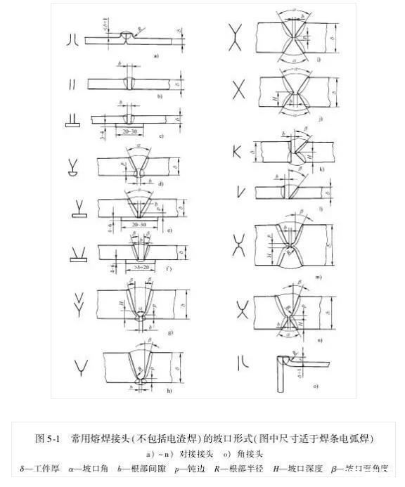
Fusion welds mainly include butt welds and fillet welds. Welded joints composed of these two types of welds include butt joints, fillet joints, T-shaped (cross) joints, lap joints and plug welded joints. According to GB/T 985-1988 "Basic forms and dimensions of gas welding, electrode arc welding and gas shielded weld grooves" and GB/T 986-1988 "Basic forms and dimensions of submerged arc welding weld grooves" commonly used The basic form of the weld groove and the above-mentioned joint form are shown in Figure 5-1. Figure 5-1 shows butt joints (see Figure 5-1 a~n), corner joints (see Figure 5 -1o~u), T-shaped and cross joints (see Figure 5 -1 v~Y and z) , A') and lap joints (see Figure 5-1 b', c') of the groove form, size, and weld metal formed by melting (indicated by thin solid lines in the figure). The relevant dimensions represented by the symbol letters are shown in Table 5-6. Table 5-6 is listed with reference to GB/T 985-1988 and GB/T 986-1988 standards. In addition to the above two standards, the choice of which groove form can also be determined by the thickness of the weldment according to industry and enterprise standards, and there is a suitable interval. For example, for the butt connection of plates with a t
- Categories:Industry News
- Author:
- Origin:
- Time of issue:2021-07-29 16:40
- Views:
The welded structure is made up of many parts, components, and parts connected by welding, so the performance and quality of the welded joint is directly related to the performance, safety and reliability of the welded structure. Over the years, the welding engineering community has conducted extensive experimental research on welded joints, which has played a great role in improving the performance and reliability of welded structures and expanding the application range of welded structures.
1. Welded joints
1) Basic types of welded joints
The main welding methods such as welding, pressure welding and brazing can be used to make welded structures. These welding methods are used to connect metal structures to form non-detachable connection joints—welding joints to form welded joints, pressure welded joints and brazing, respectively. Joints to form a welded structure. But the most widely used is fusion welding, here is the focus on fusion welding joints.
1) Fusion welded joint: The welded joint is composed of weld metal, fusion line, heat-affected zone and base metal. The weld metal is a cast structure formed by solidification of the filler material and part of the base material after melting. The structure of each part of the fusion welded joint is not uniform, and there are also differences in performance. This is because the chemical composition and metallographic structure of the above four regions are different, and the original cross-section and shape of the component are often changed at the joints, discontinuities, even defects, and different degrees of stress concentration, as well as welding residual stress and deformation. , Large rigidity, etc. all have an impact on the performance of the joint. As a result, the joint not only has uneven mechanical properties, but also has differences in physical and chemical properties. In order to ensure the reliable work of the welded structure, it is hoped that the welded joint has the same mechanical properties as the base metal. In some cases, it is also hoped to obtain the same physical and chemical properties, such as electrical conductivity, magnetic permeability, corrosion resistance, and the same gloss and color.
As far as weld metal is concerned, columnar crystal casting structure is often formed, which is generally stronger and harder than the base metal, but the toughness is reduced. For high-strength steel, using appropriate technological measures, such as preheating, slow cooling, or using appropriate heat transfer, can also obtain weld metal with required properties. Generally speaking, the strength of the weld metal may be higher or lower than the strength of the base metal. The former is called high matching and the latter is called low matching.
The heat-affected zone with small width, due to the large welding temperature field gradient, the thermal cycle of each point is very different, resulting in the difference in structure and performance. This difference is related to the structure and composition of the welded metal and the heat loss of welding. In particular, it should be pointed out that the "dynamic strain aging" (thermal strain aging) that occurs after the welding thermal cycle will deteriorate the joint performance. After pre-straining steel, aluminum, etc., the "ageing" phenomenon of brittleness will occur. This kind of pre-straining and aging occurs at low temperature (room temperature), and is usually called "static strain aging". The welding heat-affected zone will produce thermal strain after welding thermal cycle, and the high temperature of welding accelerates the aging embrittlement, so "dynamic strain aging" greatly reduces the performance of the joint, and attention should be paid to prevent it.
Fusion welds mainly include butt welds and fillet welds. Welded joints composed of these two types of welds include butt joints, fillet joints, T-shaped (cross) joints, lap joints and plug welded joints. According to GB/T 985-1988 "Basic forms and dimensions of gas welding, electrode arc welding and gas shielded weld grooves" and GB/T 986-1988 "Basic forms and dimensions of submerged arc welding weld grooves" commonly used The basic form of the weld groove and the above-mentioned joint form are shown in Figure 5-1. Figure 5-1 shows butt joints (see Figure 5-1 a~n), corner joints (see Figure 5 -1o~u), T-shaped and cross joints (see Figure 5 -1 v~Y and z) , A') and lap joints (see Figure 5-1 b', c') of the groove form, size, and weld metal formed by melting (indicated by thin solid lines in the figure). The relevant dimensions represented by the symbol letters are shown in Table 5-6. Table 5-6 is listed with reference to GB/T 985-1988 and GB/T 986-1988 standards. In addition to the above two standards, the choice of which groove form can also be determined by the thickness of the weldment according to industry and enterprise standards, and there is a suitable interval. For example, for the butt connection of plates with a thickness of 30mm, you can choose the double Y-shaped groove shown in Figure 5-1i (see Table 5-6: when using electrode arc welding, the groove is suitable for 12~60mm thick Plate; when submerged arc welding is used, it is suitable for plates with a thickness of 24 to 60 mm), or double U-shaped grooves with blunt edges as shown in Figure 5 -1 m. No matter which type of groove is selected, the quality of the joint must first be ensured, and the economy must also be considered.
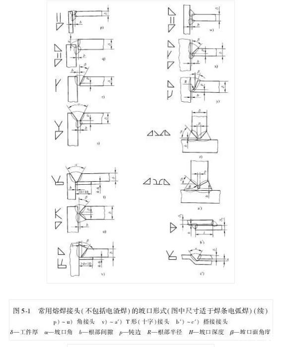
Electroslag welded joints are an important type of joint in fusion welded joints. When the thickness of the weldment is greater than 30mm, it is possible to consider the use of electroslag welding, especially for large-section welds. For example, if the thickness of the weldment is greater than 60 mm, the efficiency of electroslag welding is higher than that of arc welding. The basic forms of commonly used electroslag welding joints are shown in Figure 5-2, and the dimensions of various types of electroslag welding joints are shown in Table 5-7. When the workpiece adopts electroslag welding, the position of the workpiece should be from bottom to top, that is, the weld suitable for vertical position welding. The electroslag welding seam is formed by the welding material and the edge of the base metal being melted and accumulated by the high-temperature slag pool. Therefore, there should be stoppers on the inner and outer sides of the welding seam. Electroslag welding is suitable for welding parts with large and super large welding sections, such as thick wall pressure. Tailor welding of containers, shafts with large diameters, pipes with large thicknesses, large machine components, etc. Electroslag welded weldments usually undergo normalizing-tempering or high temperature annealing heat treatment after welding to eliminate the adverse effects of wide heat affected zone, coarse grains, and high residual stress caused by large welding heat input.
Electron beam welding joint is a special kind of joint in fusion welding joint. It uses the focused high-speed electron current to bombard the weldment, so that the electronic kinetic energy is converted into heat energy to melt the weld area of the welded joint. Its characteristic is that it can weld various special metals, large thickness, and the aspect ratio of the weld is large (up to 25:1). According to its characteristics, it is used in the welding of nuclear reactor components, some special metals in aviation and aerospace equipment, ultra-high-strength steel and heat-resistant alloy parts. Due to the small diameter of the electron beam and the concentrated welding energy, no filler metal is added during welding, forming some characteristics of electron beam welding joints. This kind of joint also has butt joint, corner joint, T-joint and lap joint. There is also a type of overlapped end similar to electroslag welding, but the weldment is tight.
2) Pressure welding joints: In addition to the above-mentioned fusion welding joints, resistance welding, friction welding, diffusion welding, ultrasonic welding, cold pressure welding and explosion welding are collectively referred to as pressure welding. Among them, resistance welding and friction welding are characterized by their high efficiency. It has been widely used in many departments. Especially in the automotive industry, resistance welding and friction welding are widely used. Spot welding (including roll spot welding) and seam welding in resistance welding mostly use lap joints. Projection welding is a variation of spot welding, but joints There are various forms, and it is necessary to design suitable and ingenious joints according to the shape and size of the weldment. High-frequency resistance welding is generally butt joints, and lap joints are also used. Resistance butt welding obviously uses butt joints. It should be pointed out that due to the development of resistance butt welding technology, it can now weld cross-sections of more than 100,000 mm². Therefore, in the manufacture of boiler pressure vessels, especially in the circumferential seams of steel pipes, For example, in the construction of long-distance pipelines for oil and natural gas (including land and sea), resistance butt welding has been applied. Friction welded joints usually also use butt joints. For other types and applications of solder resist joints, please refer to relevant information.
3) Brazed joints: There are also many types of brazed joints, but the basic types are only two types: butt joints and lap joints.
(2) Selection of fusion welding groove form
According to its shape, the fusion groove form can be divided into three types, namely the basic type, as shown in Figure 5-1b, 1 etc. are I-shaped, V-shaped and single V-shaped, U-shaped and single U-shaped, etc.; there is also a special type , Such as crimping, backing plate, overlocking and plug welding, slot welding, etc.; combined type, as the name suggests, this is a combination of the above types, most of the combined type in Figure 5-1的口口. The groove form is usually determined by considering the following issues according to the factory conditions and process requirements.
1) The processing conditions of the factory. For example, grooves such as double V-shaped, Y-shaped, single-sided V-shaped, double-single V-shaped, V-shaped, I-shaped, etc. can be cut by gas cutting, plasma arc cutting, and of course can also be processed by metal cutting methods. However, double U-shaped, U-shaped with blunt edges, J-shaped, U-shaped, and Y-shaped bevels with blunt edges generally need to be processed with edge planing machines (recently there are reports of using gas cutting to process U-shaped bevels), and the efficiency is lower than that of thermal cutting. .
2) The accessibility is good or bad. Use Y-shaped, Y-shaped with backing plate (see Figure 5-1e, f), V-shaped with backing plate, VY-shaped (see Figure 5-1g), U-shaped with blunt edges (see Figure 5-1h), etc. When welding, the joint of the mouth generally does not need to be turned over. For vessels or pipes with small inner diameters, and structures that are inconvenient to turn over, in order to avoid overhead welding and welding from the inside, this type of groove and welding seam can be used .
3) Reduce the consumption of welding materials. Generally, the amount of deposited metal is small, and the consumption of welding materials (electrode, welding wire, flux, and shielding gas) is also small, which also saves processing time. Same plate thickness: The amount of deposited metal for Y-shaped grooves can be increased by up to 50% compared with double Y-shaped grooves. Double U-shaped or UY-shaped grooves save more deposited metal. Therefore, for large thickness welded joints, this type of metal is more commonly used. The economic slope.
Narrow gap welding is also used for the welds of extra-thick parts that are not suitable for electroslag welding and electron beam welding. Groove for electroslag welding.
4) Consider welding deformation and stress. For example, single-sided welding may cause corner deformation and severe welding residual stress at the root of the weld. At this time, the characteristics of the material (base metal) should be considered, and the appropriate process and groove form should be adopted to obtain a qualified joint.
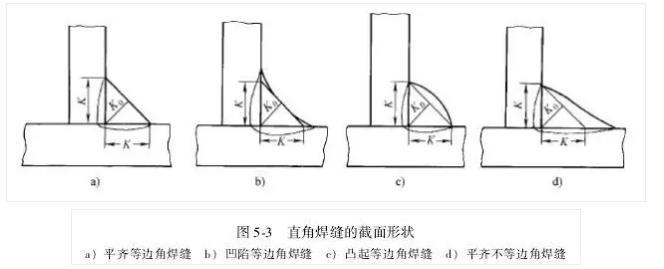
It should be pointed out that whether it is a butt weld or a fillet weld, the weld surface can be concave, convex or even, the latter is sometimes achieved by machining. In addition to the above-mentioned three types of equal-sided fillet welds, there are three types of unequal-sided fillet welds. The four types of right-angle welds shown in Fig. 5 -3, except for the three types of equilateral flat, concave and Outside the convex right-angle welds (see Figure 5-3a~c), there are also flat unequal-sided right-angle welds (see Figure 5-3d). The foot size K is the characteristic size of the fillet weld, and the foot size of the fillet weld is the right side of the isosceles right triangle inscribed in the weld, as shown in Figure 5-3.
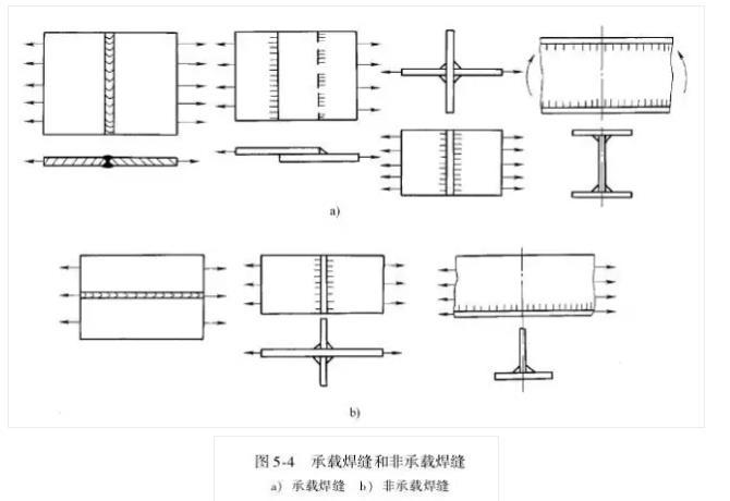
(3) Working joints, contact joints and sealing joints
The basic types of the aforementioned welded joints are mainly distinguished according to the welding process used. In fact, it is also divided according to the load-bearing condition of the welded structure of the welded structure. The welds of the welded structure can be divided into load-bearing welds and non-load-bearing welds according to whether they directly bear the load. They are also called working welds and contact welds, as shown in Figure 5-4. The former transfers the force in the structure from one part to another. The weld and the zero (structure) parts are connected in series, and the strength of this weld must be calculated. The welding seam of the latter is connected in parallel with the zero (structure) part, and it is stressed and deformed at the same time with the zero (structure) part. Even if the welding seam is damaged, it will generally not affect the safety of the entire structure. The transfer force is not the welding seam. The main task is usually without strength calculation. But strictly speaking, it should be considered as the entire joint. In addition to the welds, there are fusion lines, heat-affected zones, etc. that bear direct loads (series or parallel) or not directly bear loads (parallel). Therefore, there are documents that propose working joints, Contact joints and sealing joints. The main task of the latter is to prevent leakage, so it is mostly a working joint.
4)焊接接头工作应力的分布
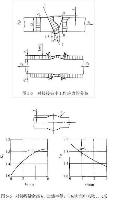
图5 -1所示的熔焊接头,如前述主要有对接接头、角接接头、T形接头(十字接头)和搭接接头,塞焊接头实际上也是一种搭接接头。在焊接接头中工作应力的分布不是均匀的,也就是存在应力集中,而各种接头应力集中的情形亦不相同。其中对接接头应力集中最小,形式最简单,力的传递也较少转折,故是最合理的、典型的焊接接头形式。即使如此,对接接头如果出现较大的余高和过渡处圆弧半径较小,则应力集中将增大,图5 -5是对接接头中应力分布的情形。图5-6则是应力集中系数Kσ随余高h和过渡圆弧半径r变化而变化的情形。
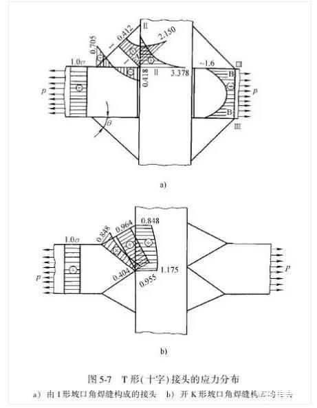
The T-shaped (cross) joint has a sharp transition from the base metal to the weld seam, the force transfer has a large turning point, the force line is distorted, the stress distribution is uneven, and large stress concentration is prone to appear. The stress distribution is shown in Figure 5-7. It can be seen from Figure 5-7a that the T-shaped (cross) joint formed by the non-grooved fillet weld, that is, the T-shaped joint shown in Figure 5-1a, has the maximum stress at the root of the fillet weld, such as Ⅰ-Ⅰ, Ⅱ -Point A of section II and point B of section III-III. If the groove is welded through, the stress distribution is greatly improved, as shown in Figure 5-7b. The T-shaped (cross) joint is also a typical fusion welded joint, and it has a wide range of applications. This joint accounts for 70% of all joints in the shipbuilding industry, so it is very important to improve its stress distribution. For the T-shaped (cross) joint formed by the fillet weld of the I-shaped groove, as the size of the weld foot increases and the angle θ decreases (Figure 5-7a), the stress concentration decreases. When the angle θ is less than or greater than 45° , Which is the unequal fillet weld of Fig. 5-3d, only the long side follows the direction of the force line (ie θ<45°) to improve the uneven stress distribution.
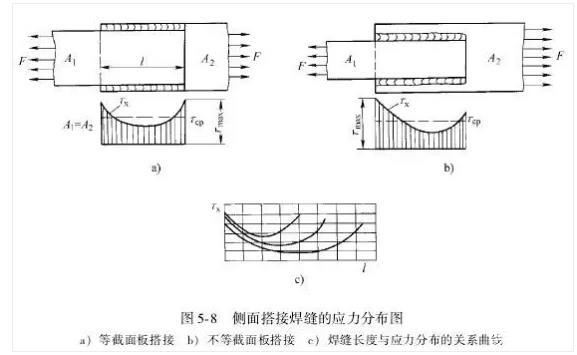
The lap joint composed of fillet welds has very uneven stress distribution. It is not an ideal structural joint form and should be avoided especially under dynamic load and low temperature. However, due to the use of lap joints, the assembly work is very simple, the pre-welding preparation is simple, and the component shrinkage is small, so it is still used in some statically loaded building structures and storage tank structures made of thin plates. It should be pointed out that lap joints can be divided into front lap joints and side lap joints. In lap joints, there is not only uneven stress distribution on the cross section of fillet welds (similar to T-joint fillet welds), but also front and side lap joints. The stress distribution in the side lap weld is also different, and the stress distribution of the side lap weld along the length of the weld is uneven, as shown in Figure 5-8. The figure shows the case of only side lap welds. A1 and A2 represent the cross-sectional area of the lap board, and the curve is the distribution of shear stress Tx. It can be seen from Figure 5-8c that when the length of the weld increases, the uneven stress distribution increases, and the middle section is hardly stressed. Therefore, some standards specify the length of the load-bearing lap weld (side lap).
Second, the design of the welded joint
(1) Design features of welded joints
Excellent joint design is one of the conditions to prevent structural damage. For joints with very complicated actual forces, the following issues should be considered when designing:
1) The welding structure should preferentially adopt the joints (welds) with simple forms, low stress concentration, and no damage to the structural continuity, that is, the joints and welds that do not make or seldom make the lines of force dense or have a turning point.
Among the above-mentioned fusion welded joints, butt joints are the most suitable for the above conditions, so they should be used first, and then T-shaped (cross) joints should be considered, while lap joints should be avoided. However, as mentioned above in some static loads, In the less important structure, it is still used for the convenience of construction.
2) Where possible, try to arrange the welded joints where the working load is small, and where the geometric size and shape of the components are unchanged.
3) The size of the foot of the fillet weld should not be too large, and the lap fillet weld should not be too long. As mentioned earlier, the stress distribution is uneven along the fillet weld section. The larger the section, the greater the unevenness of the stress distribution, so the load-bearing capacity of the fillet weld with a large section is low. However, the consumption of welding materials and man-hours increases squarely with the size of the welding foot. In lap joints, the rigidity of the front fillet weld is greater than the side fillet weld, and the actual strength is also greater. Therefore, the stress distribution in the joint lap fillet weld with the front side fillet weld is uneven, and the side fillet weld is along the weld The stress distribution in the longitudinal direction of the joint is also uneven, so special attention should be paid to important structures and joints with poor deformability.
4) The performance of the steel plate in the thickness direction (Z-direction) is poor, so it forms a T-shaped (cross) joint. If the external force is to be transmitted in the thickness direction, Z-direction steel should be used.
5) The rigidity of the welded joint is large, and the deformation of the weld is small before yielding. Therefore, high additional stress may be generated for the joint as a hinge point (such as the node of a truss). At this time, measures such as reducing the welding section and changing the welding Measures such as seam position to increase the flexibility of the joint.
6) Fully consider the conditions of the manufacturer and improve the manufacturability of the design joints. If the types of joints of the welded structure are small, the types of welding methods used are small, and the joint size is single; the accessibility during construction is good, including the accessibility during welding and the testability after welding (such as radiographic inspection to facilitate patching , Ultrasonic flaw detection has a suitable probe moving range, etc.); good weldability and so on.
7) Uneven stress distribution and welding residual stress are not considered when calculating joints. It will be introduced below that this calculation is based on some assumptions and simplifications. For harsh working conditions, such as low temperature or dynamic load, or occasions with high joint stiffness, these factors must be properly considered. For joints of welded structures that work in a corrosive environment, the detailed design of the joints also requires special consideration.
(2) Calculation of static load strength of welded joints
1) Calculation based on allowable stress method
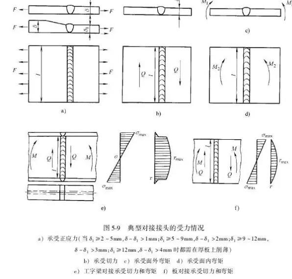
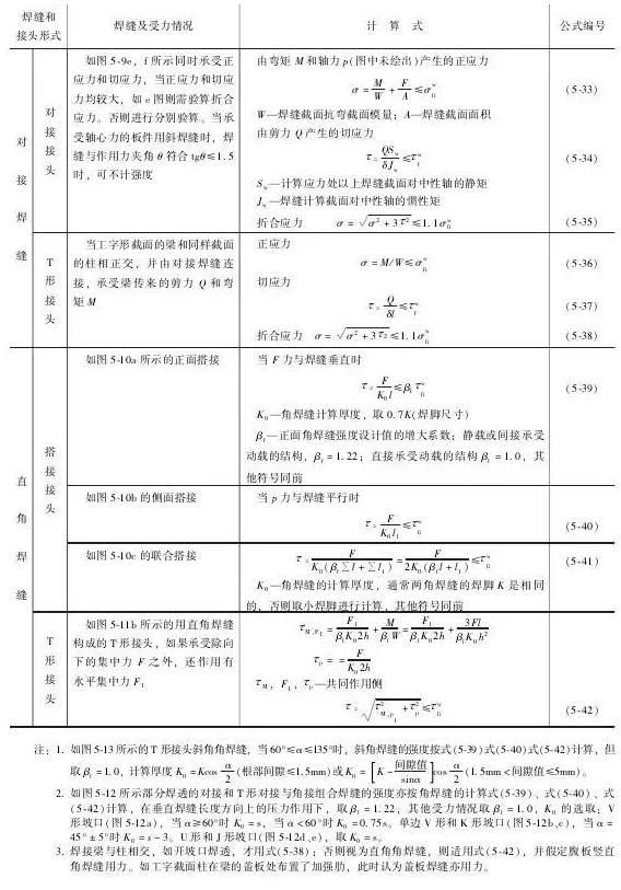
①Calculation of the strength of butt joints: Figures 5-9 show typical butt joints and their stress conditions, which can be calculated according to the formula in Table 5-8. It can be seen from the calculation formula that the calculation does not consider the stress concentration in the joint (uneven stress distribution), nor the welding residual stress, and it is considered that the working stress is uniformly distributed along the weld. It can be seen from Figure 5-9a that when two plates of different thicknesses are butt-connected and the thickness difference (δ-δ1) exceeds the specified value (according to the GB 985 standard, the allowable thickness difference is 1~4mm), it is necessary to cut a bevel on the thick plate , The bevel length L>3 (δ一δ1), the bevel can also be cut on both sides.
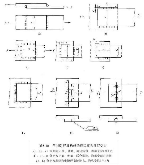
②Calculation of the strength of lap joints: Figure 5-10 shows typical lap joints and stress conditions. Plug welding and electric riveting lap joints are also listed here (see Figure 5-10g, h), in addition to this , Lap joints are composed of fillet welds, and the strength calculation of butt joints is mainly to check the strength of butt welds, the strength calculation of lap joints is mainly to calculate the strength of fillet welds. The following assumptions were made in the calculation of lap fillet welds:
First, for the shape of this fillet weld (see Figure 5-3), the height of the inscribed isosceles right triangle, namely K0, is used as the calculated thickness, regardless of the convexity and concavity of the weld, and the difference in penetration depth. ,so
K0≈0.7K, K is the size of welding foot. When the penetration depth is large, such as submerged arc welding, K0≈0.8K, or even equal to K, can be considered.
Second, fillet welds are always calculated according to the calculated section, that is, the calculated thickness (usually called the throat thickness). The shear stress damage at the section is calculated. Even if the joint bears the bending moment, the stress generated by the resistance to the bending moment is assumed to be the shear stress, see Table 5. In -8, formula (5-12), formula (5-15), formula (5-17) and so on.
Third, the difference in stress on the front and side fillet welds and the uneven stress distribution on the welds are not considered, which brings convenience to the calculation. As the side lap weld increases with the increase in the length of the weld, the degree of uneven stress increases, and the above calculation regulations limit the calculation of the length of the weld.
Fourth, limit the minimum fillet size of the fillet weld. Generally, it should not be less than 4mm. When the plate thickness is less than 4mm, the weld leg size can be the same as the plate thickness. Figure 5-10 The calculation of the strength of various lap joints is shown in the relevant part of Table 5-8.
③Calculation of the strength of T-shaped joints: As shown in Figure 5-7, T-shaped joints and cross joints can be formed by fillet welds (see Figure 5-7a). This type of joint will produce stress concentration, and it can also be formed by butt welds. If the K-shaped groove (see Figure 5-7b) is formed by the weld, the stress concentration of the latter is much smaller. Table 5-8 lists the strength calculations for the two types of welds. It can be seen that the strength calculation of fillet welds is the same as that of lap fillet welds, and the latter is the same as that of butt welds. It should be pointed out that when the T-shaped joint is under pressure (see Figure 5-11a), since the vertical plate can be tightly pressed against the cover plate, the pressure-bearing capacity is greatly improved, and the strength calculation can be carried out by formula (5-20). In many cases, the concentrated force is neither parallel nor perpendicular to the weld. The force can be divided into two parts and the strength calculations can be performed separately, as shown in Figure 5-11 d and the formula (5 -26) in Table 5-8.
2) Calculation of weld connection by limit state design method. According to GB 50017-2003 "Code for Design of Steel Structures", when welding connections are used, butt welds and right-angle fillet welds are used for butt joints, T-joints, corner joints and lap joints (Figure 5- 3), bevel fillet welds (Figure 5-13) and combined butt and fillet welds (Figure 5-12) and other forms. Welds should be selected according to the importance of the structure, load characteristics, weld form, working environment and stress state, whether penetration and different quality levels, such as butt welds of fatigue-bearing components should be penetrated and the quality of the welds should be Class I and II; although fatigue is not counted, but it is required to be as strong as the base metal, weld penetration is also required, and the weld quality should not be lower than Class II; heavy duty crane beams, intermediate work with a lifting capacity of >50t The fillet welds between the crane beams, webs and cover plates are required to be grooved and welded.
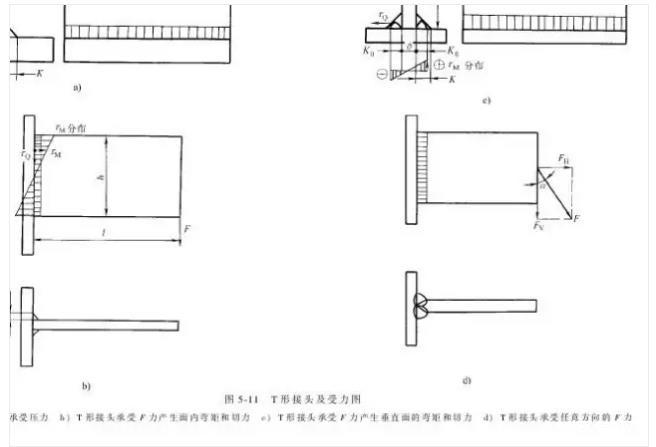
Table 5-8 Calculation of static load strength of fusion welded joints (allowable stress method)
The calculation formula of weld strength is shown in Table 5-9.
Source: Welding Technology
Note: All pictures in the article are reprinted on the Internet, and infringement will be deleted!
Tel: 0571-88780081
Mail: Firmkim@cn-huaguang.com
Fax: 0571-887 80081
Post code: 311112
Add: No. 7 Yaojia Road, Liangzhu Street, Yuhang District, Hangzhou City, Zhejiang Province (Huaguang New Materials)

Douyin QR code

We chat number

WeChat public account
©2021 Hangzhou Fujing Welding Technology Co., Ltd. all rights reserved 浙ICP备2021023610号-1 300.cn Hangzhou
-
WeChat
-
Telephone
- Service Hotline 0571-88780081
- TOP