


11-04
→2022-11-04
1. Manual TIG welding of aluminum generally uses alternating current to produce the effect of cathode atomization; for TIG welding, use DC reverse connection. When the equipment is limited to DC welding, there is usually a layer of oxide film or even black ash on the surface of the weld, which can be wiped off with a wire brush or rag. The white film formed by flux residue or oxidation on the weld surface can be wiped off with hot water with a wire brush or rag. 2. Preheating before welding: Due to the strong thermal conductivity of aluminum, manual TIG welding with a thickness of more than 10mm should be preheated before welding, but not more than 100 ℃, and the interlayer temperature during welding should not exceed 100 ℃. According to the specific situation, flame heating or far infrared plate heating can be used. 3. During the welding process, the filling point of the welding wire should not be located directly below the arc, but should be located at the edge of the molten pool, about 0.5~1.0mm from the center line of the arc. The filling point of the welding wire should not be higher than the surface of the molten pool or swing laterally under the arc, so as not to affect the melting of the base metal, destroy the gas protection, and oxidize the metal. When retracting the welding wire, do not expose the welding wire end outside the gas protection zone, so as to avoid the welding wire end being oxidized and brought into the molten pool when feeding again. During welding, if the tungsten electrode contacts the weld metal, the welding should be stopped immediately, and the metal grinding head should be used to remove the pollution and grind the tungsten electrode; before or during welding, the oxidized part of the welding wire end should be removed before welding. 4. A welding should be completed once as much as possible. When it is necessary to re-weld after stopping the welding in the middle, it should be overlapped by 10~20mm. Before the next layer of multi-layer welding, check the surface color of the previous layer of weld, only silver white is allowed; thoroughly remove defects such as surface pollution and slag inclusion. The crater shall be filled and the arc seam shall be fusion welded. Generally, the method of folding high arc extinguishing is adopted: arc is started at a uniform speed when arc is closed, and welding wire is filled at the same time until arc is extinguished, so that the weld at the arc extinguishing position is partially protruded, and the excess height is polished if necessary. When there is an attenuation device on the welding machine, the effect of this arc extinguishing method is better. Precautions when 4. welding 1. During the welding process, if there is a crack in the positioning solder joint, resulting in misalignment or gap change of the board edge, the welding should be stopped immediately, and the welding can be continued after repair. 2. The positioning weld shall be free of cracks, pores, slag inclusions and other defects, otherwise it must be removed and re-welded. Re-welding shall be carried out in adjacent areas, not spot welding in place; when the butt weld gap is not specified in the process, it may be 2 to 4mm. 3. When welding longitudinal seams, arc guiding plates and arc back plates must be placed at both ends of the weldment. The arc striking plate and the arc back plate are made of aluminum of the same grade and thickness as the weldment, and the arc crater shall be avoided as far as possible when welding the circumferential seam. 4. For the positioning weld that will be melted into the permanent weld, ensure the penetration and removal of the surface oxide layer (only silver white is allowed), and smooth transition at both ends of the weld to facilitate arc connection, otherwise it will be trimmed. When welding on cold parts, the arc should be stopped for a moment at the beginning of welding. When the edge of the base metal starts to melt, the welding wire should be added in time to ensure the penetration of the initial welding point. 5. During the welding process, the black ash and oxide on the surface of the upper weld shall be removed with a wire brush. Pay attention to the weld when welding, that is, the arc. The arc can be started at 10~20mm from the starting point of welding, and then quickly welded back to the starting point. The first layer is welded in a straight line. To get a good shape, the other layers can swing laterally and stop fusing on both sides.
11-03
→Welding of aluminium and aluminium alloys prepared before welding
2022-11-03
1. Aluminum groove processing should adopt mechanical methods (including shearing), and the groove surface should be silvery white metallic luster; if necessary, 100%PT should be carried out within the scope of not less than 50 mm on the groove and both sides. 2. The welding wire, groove surface and the range of not less than 50 mm on both sides must be cleaned (including removal of oxide film, oxide skin, pollution and unqualified oxide color). Cleaning should also be careful not to press the oxide film into the substrate, so do not use too much force when cleaning; but it is not allowed to use grinding wheel or ordinary sandpaper, because the aluminum material is very soft, resulting in residual sand particles in the aluminum material, which is easy to produce defects such as pores and slag inclusion after welding. 3. The surface of the welding wire can be scrubbed with a stainless steel wire brush or clean oil paper; the welding wire with thicker oxide skin needs to be chemically cleaned before and after welding. Chemical cleaning: soak in 5% ~ 10% NaOH solution at 70 ℃ for about 0.5~3min, then rinse with clean water, soak in 15% HNO3 solution at room temperature for about 1~2min, then rinse with warm water, blow dry with hand-held hair dryer (air compressor is not allowed, because there is water and oil in the air), and then dry in oven at 100 ℃. 4. The cleaned welding wire and weldment should be kept clean and dry, and the welding part should not be touched or blown by hand. Welders generally wear white welding gloves, do not wear dirty gloves, afraid of trouble. Pollution is prohibited before welding, otherwise it should be cleaned again, and local pollution can be partially cleaned; it is best to cover both sides of the groove with white paper. Welding should generally be carried out immediately after mechanical cleaning. If welding is not carried out within 4h after cleaning, it should be cleaned again before welding. 5. Welding parts assembly should be accurate. If the assembly is poor, the parts should be replaced, and the assembly should not be forced to avoid excessive stress. Before formal welding, the groove size should be checked, and welding can be carried out only after it is qualified. 6. When assembling weldments, try to avoid spot welding in places where stress is concentrated (such as weld intersections and corners on the workpiece, etc.).). The length and spacing of tack welds are as follows:(mm) Painting 7. Aluminum is easy to deform and collapse during welding, so it is necessary to make fixtures and shim iron before welding. When using a fixture, the front and back of the parts generally need to be clamped, and the rigidity and clamping force of the fixture should be moderate, because it is too small to control the deformation; if it is too large, the degree of restraint of the weld is too strong, which will easily lead to weld cracking. The clamping force shall be 350Kg/100mm. The soft aluminum fixture can be carbon steel or stainless steel, which can slow down heat dissipation; reinforced aluminum can be used as a fixture to enhance heat dissipation. The longitudinal seam clamp may be a keyboard type and the annular seam clamp may be a hydraulic bulge clamp. When assembling the longitudinal seam, the gap can be appropriately increased to allow shrinkage space after welding; circumferential seam (including circular flange, flange, etc.) There are some reverse wrong edges or cross edges, because the flange will collapse and deform after welding. The backing plate is generally made of stainless steel or carbon steel, and graphite can be used for aluminum welding with low requirements. The choice of liner material should also consider the effect on the cooling rate of the weld. When the aluminum plate is thicker or the assembly gap of the backing plate is larger, the gap can be sealed with clay mud and removed after welding.
11-02
→2022-11-02
Matters related to the choice of Welding materials 1 Purity of argon ≥ 99.99, dew point ≤-55 ℃ Bottled argon pressure ≤ 0.5Mpa, should not be used. (The nitrogen content of argon is ≥ 0.04, otherwise light yellow or grass green magnesium nitride and pores will be produced on the weld surface; the oxygen content is ≥ 0.03, otherwise dense black spots, unstable arc and large spatter will appear on the surface of the molten pool; when the water content is ≥ 0.07, the molten pool will boil and pores will be produced on the weld). 2 manual tungsten argon arc welding electrode adopts cerium tungsten electrode. The electrode diameter should be selected according to the welding current (when used, the tungsten electrode is generally one size larger than the required welding current), and the electrode end should be hemispherical. The method of making hemisphere: grinding the end into a cone with a tungsten electrode one size larger than the required welding current specification, clamping the electrode vertically, starting an arc on the test plate with a current 20 ~ 30A larger than the current required for the tungsten electrode and keeping it for a few seconds, so that the tip of the tungsten electrode is hemispherical. If the tungsten electrode is contaminated by aluminum, it must be re-polished or replaced; when it is slightly contaminated, large current can be increased to make the arc burn on the test plate for a while, and the pollutants can be burned. Requirements for wire feeding equipment during 3MIG welding When welding aluminum alloy with MIG, because the aluminum welding wire is relatively soft, in order to avoid biting the welding wire, it is not allowed to use the wire feeder with gear, and it is not suitable to use the push wire type. Bourdon tube is not allowed to be used for wire feeding hose. Teflon or nylon products should be used, otherwise the hose will be contaminated or blocked by abrasion. Note that MIG typically uses DC reverse polarity. 4 Selection of flux The main function of the flux is to remove oxide films and other impurities. When in use, anhydrous alcohol can be used to make a paste or directly apply the flux powder to the groove and both sides. When welding fillet welds, fluxes that are easy to remove slag after welding should be selected; fluxes for magnesium alloys should not contain sodium. 5 Selection of Welding materials for welding dissimilar aluminum When welding aluminum materials of different grades, when the drawings and process are not specified, the welding wire material should be selected according to the base metal with better corrosion resistance and lower strength grade.
11-01
→2022-11-01
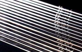
Choice of Welding materials In principle, aluminum and aluminum alloy welding wires or strips with the same composition as the base metal should be selected. Argon purity> 99.95%, try to use large diameter welding wire. Aluminum-magnesium-aluminum alloy arc welding usually recommend the use of CB-AMr2, CB-AMr3, CB-AMr6, CB- AMr61, CB-AMr63, 1557 and 1577 electrodes, and aluminum-copper-aluminum alloy recommend use 01201 and 01217 electrodes. Assembly and spot welding Due to the fast heat conduction of aluminum and aluminum alloy pipes, the crystallization is fast in the molten pool, the weld length of 10-15mm is easy to locate, and there is no gap and blunt edge, so the large residual stress caused by strong exercise after welding should be avoided. The welding positions are at 7 o'clock, 9 o'clock and 12 o'clock of the pipeline. Positioning welds are often reserved as formal welds, so problems should be dealt with in time. Before welding, remove the black powder and oxide film on the tack welding surface, and make both ends smooth. Welding parts do not require preheating. Before welding, try welding on the test plate to confirm that there is no air hole before formal welding. Using high-frequency arc, the starting point should be about 20mm above the center line, and it should be stationary for about 2-3 seconds. Then, under the condition of ensuring the penetration depth, the high current rapid welding is adopted. The welding wire shall not swing and the end of the welding wire shall not leave the argon protection zone. If leaving the argon protection zone, the end of the wire should be cut off. The angle between the wire and the weld surface shall be 15 degrees right angle. The angle between the torch and the weld surface should be maintained between 80 degrees and 90 degrees. In order to increase the argon protection area and enhance the protection effect, the large-diameter ceramic nozzle of the welding gun can be used to increase the argon flow of the welding gun. When there is spatter on the nozzle that significantly impedes the flow of argon. The spatter must be removed or the nozzle replaced. When the tungsten electrode is contaminated and irregularly shaped, it must be trimmed or replaced. The tungsten should not protrude from the nozzle. The control of welding temperature is mainly the control of welding speed and welding current. The test results show that high current rapid welding can effectively prevent the generation of pores. This is mainly due to the fast penetration of the weld during the welding process, the short heating time of the molten metal, and the less chance of absorbing gas. When closing the arc, pay attention to fill the arc pit, reduce the molten pool, and avoid shrinkage. The connection of the end point shall be welded for 20~30mm, and the air shall be stopped for 6 seconds after the arc is stopped. When rotating aluminum and aluminum alloy pipe butt welding, the welding torch should be in a slightly uphill welding position. This facilitates penetration. Thick wall tube bottom welded. Wire cannot be added. However, the welding wire shall be added in the subsequent welding layer.
10-31
→Preparation before welding of aluminum and aluminum alloys, and precautions for welding machines
2022-10-31
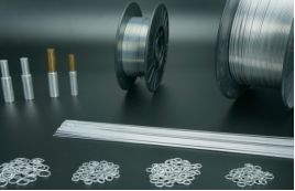
Groove processing using mechanical processing methods. The surface of the groove after processing shall be smooth without burrs and flashes. Groove form is generally V-shaped, no blunt edge, groove angle should be 70~75 ℃. Butt welds of different wall thicknesses shall have a transition section of 14O. Preparation before welding Before welding, remove the welding wire, welded pipe groove and the oil stain and oxide film within 30~50mm inside and outside the groove. The removal sequence and method are as follows: use acetone or carbon tetrachloride and other organic solvents to remove oil stains on the surface, and the removal range inside and outside the groove should not be less than 50mm. After oil stains are removed, the welding wire adopts chemical method, the groove is easy to use mechanical method, and the test tube also uses chemical method to remove the surface oxide film. On the mechanical side, the surface of the groove and its vicinity can be cleaned by filing, scraping, grinding or brushing with a stainless steel wire of about 0.2mm until the metallic luster is exposed. The cleaning range on both sides shall not be less than 30mm from the groove edge, and the tools used shall be degreased regularly. Chemical methods. Soak in 5-10% NaOH solution at 70°C for 30-60 seconds, or soak in 5-10% NaOH solution at normal temperature for 3 minutes. Then, it was soaked in about 15% HNO3 (room temperature) for about 2 minutes, and then washed with warm water. Or rinse it with cold water and let it dry completely. The welding wire that has undergone a reliable surface treatment and is not oxidized or contaminated can be directly used without the above treatment. The cleaned groove and welding wire shall not be contaminated before welding. If there is no effective protective measures, welding should be carried out within 8 hours. Otherwise, it should be cleaned again. When assembling the pipeline, the inner wall should be flush, without burrs and chips, and the misalignment should conform to B ≤ 0.5mm. The internal welded joints are not lined, and the clearance should be equal to zero as much as possible, especially at the overhead welding position. The inner wall of the pipeline should be rounded by 1~1.5mm. Welding machine and other precautions The welder must be an AC TIG welder with steep external characteristics and sufficient capacitance. Moreover, the parameters are stable, the adjustment is flexible, and the performance is safe and reliable. It should also have a device for arc starting, arc stabilizing and eliminating DC components. The current and voltage meter on the welding machine shall be verified by the metering department. Before using the welding machine, check whether the grounding is good, whether the cooling water and gas circuit are unblocked, and its various functions must be guaranteed to work normally. The welding place shall be kept clean. In addition to windproof, rainproof and snowproof facilities, relative humidity ≤ 80% and ambient temperature> 5 ℃ shall be ensured during welding.
10-30
→Physical Properties and Welding Characteristics of Aluminum and Aluminum Alloys
2022-10-30
2.1 easily oxidized Aluminum has a strong affinity with oxygen. At room temperature, the aluminum surface can be oxidized into a dense AL2O3 film with a thickness of about 0.1~0.2 m. Although this aluminum oxide film is dense, it can prevent the continued oxidation of the metal, which is conducive to natural corrosion protection, but it brings difficulties to welding. This is because the melting point of aluminum oxide (2050 ° C.) is much higher than the melting point of aluminum (about 600 ° C.), and its specific gravity is about 1.4 times that of aluminum. In the welding process, it will hinder the fusion between metals, and it is easy to form slag. Moreover, the aluminum oxide film also absorbs more water, which will promote the formation of pores in the weld. 2.2 thermal conductivity and specific heat capacity The thermal conductivity of aluminum is about four times that of steel. Therefore, when welding aluminum pipes, more heat is consumed than steel pipes. In order to obtain high-quality welded joints, it is necessary to use energy-concentrated and powerful heat sources. 2.3 easy to form hydrogen holes As well as aluminum and aluminum alloy welding pores, mainly hydrogen holes. Aluminum can absorb and dissolve a large amount of hydrogen in the liquid state, and its solubility in the molten state is 0.0069 ml/g, while in the high-temperature solidified state it is 0.00036 ml/g, a difference of nearly 20 times. Aluminum has a high thermal conductivity. Under the same welding process conditions, the cooling rate is 4 to 7 times that of steel, which accelerates the crystallization of the metal. In the process of rapid cooling of the weld pool, the solubility of hydrogen decreases sharply, and a large amount of supersaturated gas is precipitated at this time, so that hydrogen is too late to precipitate in the weld metal to form pores. Therefore, when aluminum is welded, the weld is prone to porosity. 2.4 easy to form hot cracks The linear expansion coefficient and crystallization shrinkage of aluminum are about twice that of steel, which is prone to large welding deformation and stress. In addition, the adverse effects of some impurities or alloying elements can cause cracks in joints with higher stiffness. 2.5 burn through and collapse When aluminum and aluminum alloys change from solid to liquid, it is difficult to judge the temperature of the molten pool because there is no obvious color change. The temperature during welding is too high to be detected, which often leads to burn-through or severe collapse.

10-29
→2022-10-29
Whether it is an industrial robot, a biped robot, a quadruped robot, or a robot in animation works, what is usually seen in the news is mostly a robot body. The robot control system is a hero behind the scenes, similar to the human brain. The control system is usually installed in the robot body or has a separate control unit. Now the application of robots is more and more widely, the mainstream programming of industrial robots is to teach programmers, mobile robot programming. This requires that the robot cannot be programmed to produce normally. An overview of an industrial robot system is described. An industrial robot system includes a robot body, a servo motor (or DC motor), a reducer, a driver, a controller, a teaching device, and some peripheral equipment, such as a camera, a six-dimensional force sensor, an IO module, and a welding part. If the product is single, the diversity of the product will greatly affect the efficiency of the robot. By connecting the communication device to the control cabinet or the teaching programmer, you can monitor and edit on a PC or tablet. There is no need to go to the robot's work site, but to operate/edit teaching programs in the office or management office to confirm the robot's posture, action waveform and signal status, which greatly improves work efficiency. In the production process, in order to simply calculate the daily output of workers, a counting function will be added to the robot program, so that the daily output does not require manual liquidation. Look at the data in the welding robot to know how much has been done today. If it is calculated every day, the data calculated in the robot needs to be cleared before leaving work every day or before going to work the next day, otherwise it will be calculated cumulatively. If it is not cleared, an alarm will be 4446 if the maximum count is exceeded, and the variable value will exceed the limit. If this alarm occurs, you only need to find the counted variable in the variable of the robot menu and clear it to zero. You don't have to do anything else, so you can keep working.
10-28
→The application of welding robot in welding operation replaces traditional welding.
2022-10-28
At present, most welding companies are using welding robots to weld products. The use of robot welding can not only improve work efficiency and product welding quality, but also reduce the damage of gas dust arc to workers and many other advantages. It is an essential process in the welding automation process advocated by Fujing welding. With the progress of science and technology, the firm strength of welded joints is not only the requirement of welding, but also the requirement of the beautiful appearance of welded joints. The fish scale appearance is considered to be aesthetically pleasing in current welds. Most fish scale welding applications are in the field of argon arc welding and require very skilled welders to operate. It is through the repeated process of arc starting, arc closing, re-arc starting and re-arc closing that the melted materials are pressed down one by one to form very beautiful fish scales. It requires not only the stability of the welding movement process, but also the time of arc starting and closing. Because of its good stability, welding robots have gradually replaced manual welding. Gas shielded welding also has the function of this fish scale welding. It is actually through repeated open and close the arc to achieve a weld one by one. Compared with normal short-circuit welding, it is easy to produce a little welding slag after multiple arc ignition, and the appearance will be much more beautiful. In particular, robotic fish scale welding is used in automatic cars and spinning bikes.

10-27
→Welding expert Fu Jing takes you to analyze the advantages and disadvantages of tin-lead solder.
2022-10-27
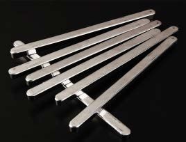
Traditional tin-lead solder has been used as a standard material for connecting components and printed circuit boards due to its low cost, easy soldering, beautiful forming, good physical, mechanical and metallurgical properties, and has formed a complete set of use processes, which has been favored by electronic merchants for a long time. Studies have shown that Pb plays the following important roles in Sn Pb solders: (1) reduce the surface tension, is conducive to infiltration; (2) can prevent the occurrence of tin plague, the so-called tin plague refers to the occurrence of a phase change from free tin (G-Pb) to gray tin ((Z-Pb) below 13 degrees C, resulting in the volume expansion of 26; (3) The rapid formation of the bond between the solder and the soldered member is promoted. Although lead-tin solder has so many advantages, because lead is a highly toxic substance, long-term use of lead-containing solder will bring serious harm to human health and living environment. Therefore, the voice of restricting and prohibiting the use of lead-containing solder is increasing. Governments have formulated corresponding regulations to restrict the use of materials and waste disposal of electronic products, making the environmental friendly requirements of electronic packaging have become a global trend. In addition, lead-free technology due to the difference of solder and the adjustment of welding process parameters, it is necessary to bring some influence on the reliability of solder joints. The SMT and MCM solder joints directly realize the electrical and mechanical connection between heterogeneous materials (mainly under shear strain), and their quality and reliability largely determine the quality of electronic products. Therefore, the reliability of lead-free solder joints has been paid more and more attention.
10-26
→How to solve the empty problem in welding!
2022-10-26
At present, consumer electronics companies in other countries, except Japan, seem to have accepted the tin-silver-copper alloy series, with the proportion of silver in the alloy being 3,0% to 4,7%; copper is 0,5% to 3,0%. The melting point of the alloy of different components is not much different, basically changing between 2l7 ~ 22l ℃, the liquid phase temperature of the tin-lead alloy is 183 ℃, the difference between the two is 34 ℃. Therefore, it is very important to closely monitor this stage at the beginning, focusing on the key variables in the reflow process, such as peak temperature, time above liquid phase temperature, immersion time, diffuse temperature, and ramp rate due to the choice of flux and solder paste, to ensure that the reflow process maintains a Cpk of 1,33 or higher. In addition, void is a common defect in reflow soldering of interconnect solder joints, especially in BGA/CSP and other components. The second generation of general-purpose solder paste formed by the progress of materials in the past two years, in addition to having a wider process window, easier application, and better appearance, the most important thing is to solve the void problem. SMT, MCM process problems. Including improper solder storage temperature, insufficient solder pad, and improper setting of reflow soldering temperature curve. In the case of lead-free soldering, the optimization of the temperature profile in the reflow process is critical to ensure a highly reliable solder connection while maintaining the lowest possible peak temperature. In lead-free soldering, voids are still a problem of concern, because in the molten state, the surface tension of Sn/Ag/Cu alloy is greater than that of Sn-Pb alloy, and the increase of surface tension will inevitably make it more difficult for gas to overflow during the cooling stage, so that the proportion of voids increases. This was confirmed during the development of lead-free solder paste, which showed that the number of voids in solder joints using lead-free solder paste was greater than that of solder joints using tin-lead solder paste. The large voids and some small spherical voids are caused by the volatilization of the flux. The ratio of the flux in the solder paste is the most direct factor affecting the solder joint voids, so there is still much room for improvement in the lead-free solder paste. As a new generation of lead-free solder paste products, Multicore(96SC LF320 AGS88) has increased the activity of flux at high temperature and achieved a great leap in technology, reducing the void level of lead-free solder joints to 7,5%.

Telephone:+86-18594983359
E-mail:Firmkim@cn-huaguang.com
Zip Code: 311112
Address: No. 82, Qihang Road, Renhe Street, Yuhang District, Hangzhou City, Zhejiang Province

Douyin QR code

We chat number

WeChat public account